Electrical Odd and Ends
These are electrical-related odds and ends (posts from the GSR forum) that I wanted to keep for future reference.
Back to BikeCliff's website.
On this page:
Stock Bulbs 
For my GS850GT, and most other GS bikes, the stock bulbs are as follows:

Headlamp (recommended):
Sylvania Silverstar H4ST - a high performance halogen headlamp, maximum
55w/65w with 7" round headlight. Can be found at just about any
auto store. |

Stop/Brake lamp: Stanley 1034 - 12v, 23w/8w
Turn Signal lamp: Stanley 1073 - 12v, 23w

Gear Indicator Bulbs: 12v 35mA, 5mm dia. available from Parts Express.
|
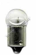
Licence Plate lamp: Stanley 67 - The full Stanley part number is A41B 67, 12v/8w.

Instrument lamp:
#194 or #158 (miniture w/wedge base) is close enough. (OEM 12v/3.4w is hard to find.) |
| In many cases, a generic 2-prong FL-522 or 552 flasher can be used in place of the stock turn signal flasher. Note that this will disable the auto-canceling feature of your turn signals. |
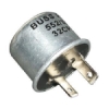 Tridon, Bussman, and others make 522 and 552 flashers. Tridon, Bussman, and others make 522 and 552 flashers. |
Wiring Color Chart/Usage

Spark Plug Cap Replacements 
thanks to Ms. SqDancerLynn1
For replacing the stock caps use 2 each - NGK XB05F and VB05F.
Cut
off a small slice (1/4 inch) of the end of the plug wire and screw in the
new plug caps. This makes a good connection with fresh
(uncorroded) wire.
The part numbers above work on my 1980 GS850G. For a full explanation of NGK plug cap part numbers see: http://www.sudco.com/spark.html
A source for "vintage" connector parts: http://www.vintageconnections.com/ 
Z1Enterprises
also has a good selection of electrical connetors, terminals, wire,
etc. Look in the electrical section under your bike model.
Compatible Stators and R/R Units:
CLICK HERE for a list of compatible stators and FET regulator/rectifiers for the GS850 and other bikes.
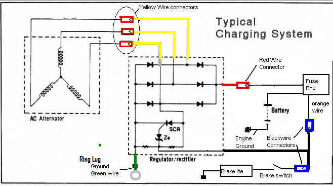
A wiring diagram for 6-wire Honda r/r units:
More on the Stator Papers 
Mr. posplayer has tweaked the first couple of pages of the Stator Papers fault finding chart to make the procedure more detailed and more thorough.
CLICK HERE to download the PDF file.
From Mr. posplayr:
Here is what I tried to do in
modifying it [Phase A of the Stator Papers Fault Finding Chart]:
-
The first step is to insure
that the is some charging going on when you raise the idle up to
2500 RPM the battery voltage should increase. If it doesn't then you
should still test and clean the connections in Step 2 and 3 but if
the stator is bad, then you will get through all of Phase A and
still have low output.
Battery Charging 
Here is a very thorough article about how to initialize and charge a motorcycle battery:
http://bmwmotorcycletech.info/newbattery.htm
Regulator/Rectifier Diode Test
I performed a diode test on a good spare 6 wire Honda Shindengen r/r unit. These are my results.
Here's what I get on my diode setting:
1) Starting with the (+) lead on the sense wire:
All (-) connections to red output, green ground, and yellow inputs read "+OL".
2) Reversing the leads, putting the (-) lead on the sense wire:
The (+) connection reads:
Red output = +OL
Green ground = ~ 1.5v
All yellow inputs = +OL
3) With the (-) lead on the red output:
The (+) connection reads:
All yellow inputs ~0.54v
Green ground ~0.99v
Black sense +OL
Reversing the above reads +OL on all combinations.
4) With the (+) lead on green (ground) wire and (-) lead on the yellow wires should read ~.54
Should real "+OL" when connections are reversed.
5) Probing between all of the yellow inputs in any combination reads +OL.
Note that the step 3) "all yellow" inputs are the same as the yellow,
blue/white, green/white (or red/white) wires connecting from the stator.
Also note that in step #3, when testing between the red output and
"yellow" input wires, the "~0.54v" readings can vary depending on the
r/r model and the multimeter. As long as the readings are consistant,
anything between ~0.4v and ~1.0v should indicate a good circuit. If one
of the three readings is significantly different from the other two
(i.e. two read .4 and the other one reads .7), the the r/r unit would
be suspect.
Connections to the sense lead on a Honda r/r are irrelevant for diode
tests and are included for information only. Steps #3 and #4 are the
critical tests. This same test is valid for 5-wire r/r units, just
disregard the "sense" wire information.
More On Coil Relay Modification 
Here are a couple more PDF files by Mr. Matchless that help explain the coil relay mod and other uses for relays.
Relay Modification For Older Bikes
Ignition Coil Relay
My Coil Relay Mod Story - by BassCliff
Under
my tank there are two orange/white wires coming out of the wiring
harness, one going to each coil. I cut both of them. The two o/w
wires that go back into the harness go up to the kill switch. The
other side of the o/w wires go to the two coils. On both sides I
stripped the wires a little, wrapped them together, tinned them with
solder, and crimped them both into a spade connector. Now both of
the wires going to the coils are crimped into one connector. Also,
the two o/w wires coming out of the harness are crimped into one
connector. I poured over the wiring diagram for my bike to make sure
it would work this way. It did.
[The
following paragraph is somewhat speculative. I'd have to check a
wiring diagram to be sure.] Some coil relay mod diagrams show that
one of the o/w wires going back into the loom is left unconnected.
While this doesn't affect the operation of the relay mod on the
coils, it would seem to disable the kill switch. My kill switch still
works.
Then
I ran 2 wires (both red in my case, you may want to use different
colors) all the way back to the relay next to my battery box. I had
to be careful to label the wires correctly so that I know which one
goes to the coils and which one goes back into the wiring harness.
I
took a Sharpie and wrote on the plastic covers of the spade
connectors (you've seen them on my r/r replacement guide and such).
I came up with a little mnemonic to remember what goes where.
There
are 4 connections on the standard relay; 30, 85, 86, 87. The power
from the battery gets connected to #30. Then, like the car Mazda
made years ago - Mazda GLC, the Great Little Car - I think "G-L-C"
for the rest of the connections. G for ground. L for loom (another
name for the wiring harness), and C for coils. (+)=30, Ground=85,
Loom=86, Coils=87.
In
this manner I used my Sharpie to write "+", "G",
"L", "C", on the connections at the relay. The
connections at the relay are all female spade connectors since the
relay has the males. If I ever want to take the relay out of the
circuit I can...
-
Pull
the fuse on the hot wire to the battery.
-
Disconnect
the "C" and "L" connections from the relay.
-
Use
my short jumper, with male connectors at each end, to reconnect (C
and L) the coil wires back into the harness.
My
clutch interlock was not affected at all. I still have to pull the
clutch in to start my bike even if it is in neutral.
If
everything else is well-maintained in your engine, then even if you
have some loss at the coils, there is enough spark to start
combustion. But a good, fat spark gives you the most efficient burn.
It's usually when the voltage falls below 10v that you really start
having problems, especially if there is anything else wrong with your
motor. These engines are so well designed that they can take a LOT
of abuse before they quit running.

General Spark Plug Information 
Reading spark plugs, caps, gaps, etc:
http://www.totalmotorcycle.com/maintenance/sparkplugs.htm
Also see: Spark Plugs, How to Read
GS850 Color Wiring Diagram Erata 
Originally Posted by Mr. Steve
The wiring diagram in many Clymer manuals is incorrect.
I have seen problems with many different versions of these Clymer diagrams, I have not checked any of the Haynes pictures.
The problem is in the power wire. There is a red wire that goes from the battery to the fuse panel, 4th and 5th fuses. Good.
From the right side of the 4th fuse it goes to the ignition switch. Good.
Looking
at the connections in the ignition switch, it then comes out the gray
wire, which goes halfway across the page, then up and branches out to
feed the lights. NOT GOOD.
The gray wire and the orange wire are
switched at the ignition key. It is the orange wire that then goes back
to feed the top three fuses.
If
you switch the positions of the orange and gray wires, the rest of the
diagram is OK. Also note that there were features added that do
not show up in this diagram, like the sidestand switch in the '82 and
newer models.
(Here is a link to the correct color diagram.)
Simplify The Wiring Diagram 
Originally Posted by Mr. Steve
A quick tutorial on how to view the diagram to make it look easier:
Find
the battery. There is a line that goes from there to the fuse panel.
Follow the path through the main fuse to the ignition key, then back to
the fuse panel, where that power wire feeds three other fuses. The top
fuse only powers the head light, tail light and meter lights, so if you
have problems with lights, look at the top fuse. The second fuse only
powers signal devices. These devices are the turn signals, brake light
and horns. The third fuse only powers the igniton. You have now broken
up the diagram into three considerably smaller sections, making it much
easier to track what is going on.
Diagnosing Slow Cranking 
Originally posted by Mr. Steve
To
help diagnose this problem, you will need a voltmeter and probably a
helper. It does not matter if it is analog or digital. Clip the black
wire of the meter to the negative terminal of the battery. Touch the
red lead to the positive terminal (make sure it's the terminal, not any
of the wires that might be connected), note the voltage. Press the
starter button (have your helper pull the clutch and push the button
while you handle the meter), note the voltage. If it dropped below 10
volts, you need a new battery. Yeah, it may be "charged", but it does
not have enough capacity left to handle the starter. You can also prove
this by using jumper cables to connect your bike to your car (with the
engine not running) and cranking again. If the starter spins now, you
know it's your battery. If the voltage did not drop that much, continue.
Now
touch the battery terminal on the starter solenoid (again, the
terminal, not the wires), note the voltage when you press the starter,
it should be the same as the battery terminal voltage. A drop here
would indicate bad connections. Clean them and try again. Now touch the
red meter lead to the bolt that holds the wire to the starter, do the
same tests. Again, you are testing for bad conections.
It is
possible, though, that the starter itself is dragging a bit. You will
have to remove the starter from the bike and connect jumper cables to
it and a good battery to test. Be careful when you make that last
connection, though, the starter has quite a bit of torque and will try
to jump out of your hands.
Also keep in mind that getting power
to the starter is only half the battle. You also need to have reliable
ground connections, so make sure the starter is securely bolted to the
engine, and that you have a good connection from the engine block to
the battery. Most bikes will have a wire (cable) from the engine to the
chassis and another from the chassis to the battery, so make sure all
the connections are good.
Igniter/Signal Generator/Coil Test 
Originally posted by Mr. Billy Ricks
This is for an '85 700 but you can probably use the same tests for your bike.
Here's
how to check the ignitor. Remove spark plugs 1 & 2 and ground them
to the motor so they will fire when they get power. With the ignitor
facing you, the plug on the right side of the ignitor is where the
signal generator plug fits. The two terminals on the right side of that
portion of the ignitor will be pin 1 at the front and pin 2 at the
back. The two left pins will be pin 3 in front and pin 4 at the back.
Turn the ignition switch on. With a multitester set a the X1 ohm range
put the + probe on pin 2 and the - probe on pin 1. Plug number 1 should
fire. Next put the + probe on pin 4 and the - probe on pin 3. Plug
number 2 should fire. If this happens the ignitor is good and the
signal generators are suspect.
As for testing the pickups,
signal generators, measure the resistance between the two wires on each
pickup. You should get somewhere around 130-200 ohms. If the resistance
is infinity or less than spec they are shot.
To test the coils
put one probe of the multitester on each of the terminals on the
primary side of the coil. You should get 3-5 ohms. Check the secondary
windings by placing one probe into each of the plug wires coming from
one coil. Those would be 2 & 3 from one coil and 1 & 4 for the
other. You should get 30-50,000 ohms for stock coils and 15-20,000 for
aftermarket.
Here is another procedure to test the igniter by Mr. almarconi
Remove the spark plugs of #3 and #4 cylinders, fit them into the plug caps, and place them on the cylinder head.
Remove the frame cover on the right side and disconnect the lead wire from the signal generator.
Connect (+) lead of voltmeter [set to ohms] with blue lead wire on the
ignitor side, connect the (-) lead on the voltmeter with the green lead
wire.
The moment the test leads are connected, the electrode of spark plug of #4 fires. The moment the test leads are disconnected, the electrode of spark plug of #3 fires.
Stator Rewinding 
Using the stator rewinding guide in the Garage Section of The GS Resources website, Mr. Nerobro documents his stator rewinding experience in this thread on the GSR Forum.
Lighting Upgrades 
Here
are a couple of links with guides to help you turn your single-filiment
turn signals into dual-filiment running light/blinker combiniations.
Greg Bender - Turn signals as running lights
1157 turn signal mod - BigCee Engineering
Check out this aftermarket turn signal conversion kit from electricalconnection.com:
http://www.electricalconnection.com/other-lighting/tsk-star&sport.htm
Flashing LEDs from Hyperlites should make you more visible:
http://www.hyperlites.com/
Convert Gauge Lights To LEDs 
(by Mr. Matchless)
In this guide, Mr. Matchless shows us how to remove the incandescent bulbs from the gauge cluster and replace them with LEDs.
Gauge Illumination Lamps To LEDs
If your gauge cluster has a single turn signal indicator bulb, here is some helpful information from Mr. Steve:
If you have a single [turn signal indicator] bulb in the instrument panel, it is fed by two hot
wires from the turn signals. The indicator bulb acts as a current
limiter and uses the turn signals on the other side as a ground wire.
When the left turn signals are on, the indicator will also light, but
won't pass enough current to light the right-side signals, so it uses
them as a ground. Same thing for the other side.
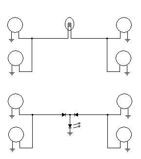
If you want to use a single LED for your indicator, there is no problem, as long as you use a couple other LEDs to feed it.
Here is a diagram I did for somebody doing the same thing some time
ago. It only shows the lights, not the wires that come from the
controls, etc., but it shows the original setup with a standard bulb,
then how to wire in two LEDs that will allow the use of a single LED in
the instrument panel.
How To Repair Your Wiring Harness 
Originally posted by Mr. Joe Guilbeau
Here are some how to tips on repairing the wiring harnesses and how to go about it.
The
connectors that were used on these old GS's were predominately Molex
connectors. Time has improved the technology and I will share a link
with you.
The following source is a pretty cost effective way to
replace those pesky Molex connectors (White, Green and Blue) that tend
to crumble with age.
Use General Motors Delphi division's
WeatherPak connectors, weather-proof with seals. These can be had (for
a bit of a steep price) with the pigtails included. That is, there is a
connector that already has the wire crimped to the the connectors and
seals and these are already seated into the connectors for you. You
will pay extra for this... OR
You could go to this website and pay for the crimping tool, the extraction tool and the separate components.
http://rjminjectiontech.com/?p=12
You
basically slide a seal over the end of the wire that you want to
terminate, then strip off 3/16-inch and then terminate that wire with
the crimp tool, then crimp the seal with that same crimp tool and
insert the Pin/Socket into the proper housing and Pin/Socket position.
This WILL cure the majority of your wiring problems.
These
same connection can be had a a pigtailed pre-assembled package and you
would simply cut your Molex connectors out of the harness and replace
with the respective WeatherPak connector by using bare metal Butt
Splice connectors, crimping into place (after sliding Heatshrink tubing
over the individual wires). After crimping I solder the connection
making sure that the solder is wicked into the Butt Splice Connection,
and then apply some liquid electrical tape to cover all metal exposed
parts, Then heat shrink this extending 1/2-inch out from the ends of
the Butt Splice connector. You are good to go.
Here is a link for the pigtail WeatherPak connectors....
http://www.whiteproducts.net/pigtails.shtml
For a one stop connection there is an eBay outfit that will sell a kit for all you need for one bike:
Ebay Store: HiPo-Parts-Garage_Weatherpack-Electrical-Parts
And the crimp tool:
Ebay Store: HiPo-Parts-Garage/Weather-Pack-Economy-Crimping-Tool-20-14ga
The two links above will suffice for most of anything you might need to fix any problems with wiring harnesses.
Not exactly cheap, but peace of mind is worth something.
(Author's update) Some (legitimate) concerns were raised in this [discussion] and so I thought
that the easiest way to add to the knowledge base was to edit this post
and offer some additiional methodologies for splicing wires together.
Namely Tyco's Soldersleeve
Here is Digikey's Catalog Page...
http://dkc3.digikey.com/PDF/T082/P2121.pdf
No crimping required, simple and straightforward process, clear shrink tubing allows inspection at later dates if desired.
There are many ways to skin a cat, if done properly most any of these
methods will work for you, if done improperly, most of these methods
will fail for you.
I will simply add to this post from time to time to give the dear
reader options that should suffice to get the your particular job done
to your satisifaction level.
For instance, the Soldersleeve's work quite nicely with regards to
integrity and reduced bundle size. By the way, Microtorches work very
well on these kinds of repairs, you can take some of these splices with
you in your tool kit, and be the darling of the techno geeks when some
poor slob has a wiring melt down on the side of the road. Whip out the ultra cool torch, a bit of wire, your handy dandy T-Stripper ( http://www.mytoolstore.com/ideal/ide11-03.html ) and volia!
Cleaning Your Wiring Harness 
Originally posted by Mr. Matchless
I
pulled the tape off the wiring loom, removed the two redundant wires
for the third phase charging and cleaned each wire full length with
benzine.
Sprayed out all connectors and bullet connector boots
with brake cleaner. Then dipped contacts in hydrofluoric acid for 5
minutes to clean the brass, dipped in clean water, sprayed with brake
cleaner and finally sprayed with contact cleaner, left overnight and
again cleaned each connector and conector block with brake cleaner. All
connectors are now bright brass and the bullet connector boots look
close to new.
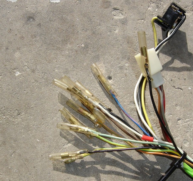
(Optional) Next step is to add new wires for coil and horn relay mod as well as a 12v accessory point and then wrap the loom up.
As the most problems on these old bikes are usually electrical or fuel related I am trying to do this properly.
When you unwrap use "benzine" to clean the old glue and dirt of the plastic wires. It will not harm the plastic.
If
you decide to rewrap use a well known brand of insulation tape, the
cheaper types have the adhesive loosen in hot weather. The types
without adhesive becomes a headache when it unwraps at the ends.
Stay
away from wrapping with "rubber" tape, that usually is the expensive
type with no adhesive and is stretched and bonds into itself. You will
learn new words if you ever have to open the loom sometime in the
future!
If you decide to use the split sprague type conduit for
the wires, just note that it is going to be much wider in diameter at
the head (due to the ridges) and coils area and may cause problems.
Where you have enough space it will look very neat.
Also note
stationary wires are OK in a loose tube, but in areas such as the head
they are pulled and moved and may chafe individually against each
other, when wrapped they bend and move together as one. Wires loose in
a tube may feel better on the steering, but it is not really a good
idea.
If rewrapping the complete loom, pull it out, put it on a
large wooden board and put some nails at the ends and junctions. Take a
few photos.
Unwrap and use cable ties to hold them together at
intervals and at the branches. Clean the wires with a benzine soaked
cloth. Inspect the wires and replace if too short or damaged. Decide if
you are replacing all connectors and connector plugs and have them at
hand. Remove wires such as the 2 stator 3rd phase wires that is not to
be used again. Add you coil, headlight and or horn relay wiring. Relace
any wires with heavier gauge if this is required.
Now make sure
that your wires are clean, straight without any kinks and nicely laying
alongside each other and eleiminate any crossovers. Keep them in place
with a couple of cable ties.
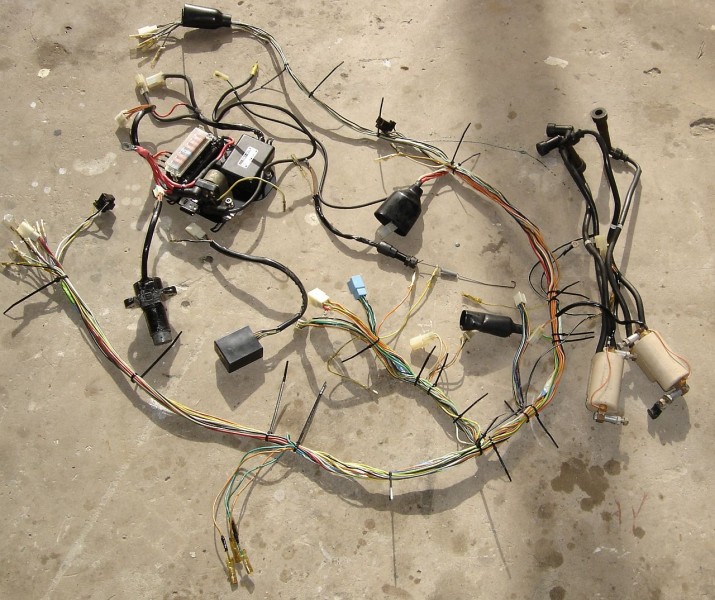
Some
looms have a split sheathing around the wires under the tape to protect
the wires, especially in areas where there is movement. Replace this or
reuse, but fold it over as tightly as possible to keep the diameter
down. Pull the wire tight at each end of the tubing and wrap the wires
for an inch or so and over the tube.
Now start wrapping from the
center moving towards the ends, so as to eliminate any slack and
crossings causing bulges being trapped, At the end overlap the wrapping
a few times and move back a bit so as to not leave an end that can
start peeling back. Always stretch the insulation tape so that it just
starts stretching as you wrap. Try to keep the wires parallel with each
other, crossing over is untidy and makes the bundle thicker. Remove the
cable tie as you get to it.
Finally make sure you have wrapped
the complete loom and the branches as it was done originally. This will
keep out water grime, protect the wires and make the loom look good
again.
Mr. Nessism adds:
Deoxit works well to clean electrical contacts...CLICK HERE for a source and more info.
There are different formulas. I think the D100S version has the strongest cleaning power.
Testing The Ignition System 
by Mr. Matchless
Properly localizing a problem with the ignition is sometimes a bit confusing and the following below should of assistance:
- Basic
test, remove spark plugs. Fit them to the plug HT leads and ground them
to the engine. Turn engine with starter and see if plugs spark. If any
one spark plug does not spark swap it out. If the spark seems good on
all 4 plugs, the ignition system is very likely in order. If spark is
not present or very weak proceed with the following tests.
- Remove the tank, left side cover, seat and signal generating unit (pickup) cover at bottom right of engine.
- A good habit is to check the coils and igniter to see if they do
not get very hot once the ignition is switched on, as this will most
likely be the indication of a failed component of faulty connection or
wire.
- If the spark is weak but present, inspect the HT leads and plug
caps. Suspect coil wires and spark plug caps, or voltage at the coils
and thus the battery condition. It could also be due to coils with
partially shorted windings, but do not jump on this cause immediately,
and they may get hot.
- Overheating coils with no spark may also be due to them getting a
permanent full ground either from a faulty igniter or a grounded and
pinched wire. Disconnect the coil plug connectors and proceed with
tests.
- Measure the battery voltage directly across the battery terminals.
If lower than approximately 12.6V first charge battery fully before
proceeding.
- Next measure voltage over the coil connector plug, orange/white
wire and the battery negative terminal. If lower than 12 Volt inspect
the wiring for poor contacts and localise cause of voltage drop.
- Again measure directly across the battery, but pull off the spark
plug leads to prevent engine from firing and swing with starter. While
starter is turning the voltage should stay at least above 11 Volt. Also
swing the starter with the headlights on to see that the voltage does
not drop significantly at the coils while the starter plus headlights
load the battery, which could prove that even if your battery is fully
charged, it cannot give full or sufficient current and is on its way
out or your starter may be drawing excess current (usually unlikely if
starter is spinning at full speed) and pulling the battery down. If it
drops much lower, charge battery fully or have it load tested and
replaced if faulty.
- If all is well up to here you can assume your battery and the positive feed to your coils are in good order.
- With the coil plug connectors disconnected, use an ohm meter and
measure the resistance of both windings on each of the coils. Exact
resistance measurements are not too important, but continuity of the
windings close to the approximate resistance values given indicates
that the coils are in good condition. It must be noted that it is
possible for the coils to only show up a fault when at higher operating
temperatures, but this does not happen frequently.
Ignition coil resistance:
Between the two HT plug caps of the same coil, secondary HT winding, approximately 30 - 35 K ohm
Between the orange/white and white on the first coil and orange/white
and black/yellow on the second coil, primary winding, approximately 2-5
ohm. If this test is within limits you likely have two good coils.
- Locate the igniter and disconnect the plug with the blue and green
wires coming from the signal generator (pickup) at the right bottom of
the engine. Test the resistance across these wires coming from the
signal generator pickup coils, it should be approximately 250 - 360
ohm. If this is in order you have proved the pickups and the wires to
be good.
- The little back box or igniter is now tested as follows. With the
ignition on, kill switch on, test for 12 Volt DC between the
orange/white and the black/white wires in the plug going into the
igniter. This proves that it is getting the correct voltage.
- The next step is to prove whether the igniter is powering your
coils. Remove all 4 spark plugs and connect the HT lead caps to a spark
plug #1, #2, #3 and #4 which is grounded and located to enable you to
see the spark. Ensure all the connector plugs are back in, except the
one with the green and blue wires from the signal generator.
- To simulate the small voltage generated by the pickup coil, prepare
an ordinary 1.5V dry cell with two wires red for positive and black for
negative. Connect the negative black wire from the dry cell to the blue
wire on the connector plug going into the igniter. Switch on the
ignition and kill switch to power the igniter and briefly touch the red
wire from the dry cell positive to the green wire connector going into
the igniter. You should see a spark on plugs #1 and #4 when you touch
the wire and on #2 and #3 when you remove the wire. If this works your
igniter is in a working condition.
- One other check that is often overlooked. Run the bike at night
with all lights off in a dark area and check that no sparks are jumping
from the HT leads to the frame or tank. If so they may need replacing.
- At this stage if all tests have passed you MUST get a spark at all
the plugs when everything is reconnected and the engine is turned with
the starter.
- If a spark that was previously missing has mysteriously appeared,
have a very good look at your wiring and connectors, as something may
be making intermittent contact and corrected itself temporary when you
moved the wires.
- If there is a spark, but the engine will not fire, it could be due
to ignition timing, valve timing or fuel problems. Ignition timing and
valve timing problems are more likely on a bike that has not run yet
after being disassembled and more unlikely to be the cause if the bike
was not taken apart and was running before.
- A quick test with a few drops of fuel directly into the cylinders
before replacing the spark plugs and then trying to start will prove it
to either the fuel system or ignition system.
- If
the engine then starts and runs for a few RPM's the ignition is correct
and you need to look at the fuel and carburettor side.
- If the engine does not fire, but occasionally gives one load pop
through the carburetors or even exhaust, it may be igniting when the
valves are open, the valve timing may be a problem, cam chain or
swapped wires from pickup - plugs firing at wrong time.
- Other reasons could be extremely low compression, too tight valve
clearances, thus not closing fully (usually unlikely on all cylinders
at the same time, but plausible), carburettor faulty or dirty, fuel
line, filter or petcock faulty. Filter can cause an airlock if not
positioned properly to allow free gravity feed.
- Then finally the ignition timing must be set properly. At less than
1500 RPM connect a timing light to #2 or # 3 spark plug and check that
the timing marks line up for 2-3 on F, then move to #1 or #4 spark plug
and check that marks line up for 1-4 on F. Check the advance by pushing
revs up to 2350 RPM and the timing marks should both line up on the 45
mark behind the signal generator mounting plate through the sight hole
at the top. The three mounting screws can be loosened and the mounting
plate can be moved slightly in the elongated holes to meet this.
Points Timing 
(by Mr.earlfor)
To
adjust timing with the bike running, you need a dynamic timing light.
To set the static timing (bike is NOT running) all you need is a 12
volt lightbulb and two wires so you can connect it.
Here's the proceedure for
timing the 750. The points are located under the round cover on the
right end of the crankcase/crankshaft.
Setting the points gaps
The round 6" plate that both
sets of points are mounted on (breaker plate) is held in place by three
screws located at 12, 4 and 8 oclock. Loosen the 3 screws on the
breaker plate. Note that the screw at 12 oclock is in a slot. Rotate
the breaker plate until the 12 oclock screw is centered in the slot.
Tighten the three screws.
We will replace the left side set of points first (located at 9 oclock position) These are the points for cylinders 1 and 4.
Take a 19 mm wrench and rotate
crankshaft until points are at widest gap. Unscrew hold down screw on
pointset and remove points. Note the white wire that goes to the
pointset and the placement of the insulator. The insulator must be
correct or the points will be grounded out and will not work. Put the
new points onto the breaker plate, set the gap to 14 thousandths, and
lightly tighten the hold down screw. Install white wire. Rotate
crankshaft once again with 19mm wrench until points are at widest gap.
Check that widest gap remains at 14 thousandths. Adjust and retighten
holddown screw if needed.
Rotate crankshaft until rightside points are at widest gap (for
cylinders 2 and 3) Remove old points and install new points and set gap
at 14 thousandths. Note insulators on black wire installation. Rotate
crankshaft with 19 mm wrench again stopping at widest gap. Recheck gap
as you did with the left pointset. Adjust and retighten hold down screw
on points if needed.
You have just completed setting the points gaps.
Next is the timing:
Timing for cylinders 1 and 4 (the left set of points)
With 19 mm wrench, rotate
crankshaft while looking through the timing window and align the mark
that looks like |F1 with the timing mark on the engine case. (The line
[|] preceeding 'F1' is the mark - |F1.)
Note: Some bikes will have a stationary timing mark on the engine case
and some will have a mark on a stationary timing plate that can be seen
through the timing window.
Connect a continuity light wire lead/clip to the white wire clip on the
left pointset. Clamp continuity light probe tip to ground on the bike
or battery negative terminal.
Turn ignition switch to on. (Do not attempt to start bike, just switch ignition to on.) The continuity light should be on.
Loosen the three screws on the
breaker plate located at 12, 4 and 8 o'clock. Rotate breaker plate
until continuity light just flickers out. Retighten the 12, 4, and 8
oclock screws on the breaker plate.
Unclip continuity lead from left pointset.
Timing for cylinders 2 and 3 (the right set of points)
Rotate
crankshaft with wrench until you see the timing mark F2| becomes
aligned with the stationary timing mark on the engine case. Connect the
continuity light lead to the black wire on right pointset. The ignition
should be switched on and the continuity light should be on.
The
right pointset is mounted to a breaker half plate. You will see that
you can loosen the mounting screws on this breaker half plate and this
will allow you to move the right pointset. This will adjust the timing
without changing the points gap. When you rotated the complete breaker
plate for the left pointset to get the continuity light to flicker out,
thats what you did. You adjusted the timing on cylinders 1 and 4
without changing the gap on their pointset.
Unfortunately,
the whole breaker plate being rotated moves BOTH sets of points, so
that is why you must set the left side first and that is why the right
side is mounted on its own independent half breaker plate.
SOoooooo....
Smile! Loosen the breaker half plate on the right side and rotate as
needed to cause the continuity light to just flicker out. Tighten the
half plate back down when satisfied with the adjustment. Smile!
Remove continuity light and HOPEFULLY, start bike.
Mr. gearman adds:
I
seem to have better luck using an ohmmeter instead of a continuity
light for static timing. I'd also recommend replacing the condenser(s)
and the point am lube felt (if used) while your at it. Here's a little
vid of some points in action: http://s146.photobucket.com/albums/r247/gearman22/tutorial/?action=view¤t=points.flv

Simple Wiring Diagrams for those of you who might be building a new wiring harness for your bike:
http://livetorideridetochurch.blogspot.com/2010/09/i-love-these-types-of-diagrams.html
Right-click and save this diagram:
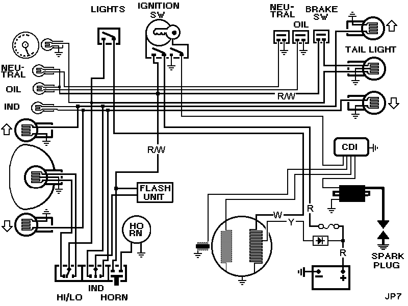
Here's a diagram drawn up by the GSR electrical guru, Jim (posplayr) for a GS550 but can be adapted for other bikes:
550_Schematic.pdf (about 350kb)
Charging System Health 
Mr. posplayr has put together a comprehensive tutorial on keeping your Suzuki GS charging system healthy:
GS Charging System Health (PDF file <1MB)
Quick Test (Procedure by Mr. posplayr)
Sometime people get a little confused in the details of doing the stator
pages and sometimes they forget to check their battery. So just to help
things along if someone is a bit confused and needs a sanity check.
These tests are NOT mandatory as long as you know you have a good battery and can follow your way through the stator pages. Otherwise it is just a nice real quick test.
NOTE: THIS IS NOT TO
REPLACE THE STATOR PAGES. IT IS JUST A QUICK SANITY TEST to see if the
battery is good enough to proceed with the STATOR PAGES. The first part
of the Stator Pages will actually measure how good your connections are
and goes well beyond this QUICK check.
Quick Test Steps:
1.) key off................Normal 12.7 volts-12.9 volts
2.) key on (but not cranking with lights for 10 sec).....Normal 12.2-12.5 volts
3.) at idle (1500 rpm).....12.6volts - 13.2volts
4.) at 2500 rpm 13.5 -14.0 volts
5.) at 5000 rpm.....14.0 -15.0 volts
6.) key off.....slightly higher than measurements # 1 (12.8-13.0 v)
QUICK TEST Diagnosis Summary:
Basically Step #1 and #2 is making sure the battery is charged
and in good health. The drop should be about 0.5 volts for normal
headlamp and coil load (without cranking the starter)
Step #3 is get a baseline starting voltage. This will vary some
depending upon your idle and the particular R/R you have. It could be
lower than the off voltage or as you idle up it will increase to 13.0 v
Step #4 by the time you get to 2500 RPM you should have close to
the maximum output voltage even if you have bad connections. You are not
pushing as much current and this shows that the stator is likely good.
Step #5 by the voltage at 5000 RPM being higher than at 2500 RPM
you have a pretty good indication that your connections are good. If the
voltage at 5000 drops from 2500 you have bad connections. If you
already checked the grounds then it is likely in the positive legs
between R/R(+) and Battery (+) check fuse box and the large bullet
connector to the battery. The voltage climbs above 15.0 V it is likely
the R/R not regulating and is bad bad.
Step #6 If after running for a few seconds in a charging state
the voltage to the battery should have risen a bit. If it is lower than
where you started then you did not charge at all, Again this will vary
some what depending upon how long you let the bike run.
Fuel Gauge Test - A quick troubleshooting guide.
Stay tuned for more odds and ends. 
Back to BikeCliff's website.


